What is a Transmission Electron Microscope (TEM)?
- This is a powerful electron microscope that uses a beam of electrons to focus on a specimen producing a highly magnified and detailed image of the specimen.
- The magnification power is over 2 million times better than that of the light microscope, producing the image of the specimen which enables easy characterization of the image in its morphological features, compositions and crystallization information is also detailed.
- Early discovery of cathode rays like electrons by Louis de Broglie in the early 1920s, paved way into the development of an electron microscope where they used a beam of electrons creating a form of wave motion.
- Magnetic fields were used as lenses for the electrons. With these discoveries, the first electron microscope was later developed by Ernst Ruska and Max Knolls in 1931 and modified into a Transmission Electron Microscope (TEM) by Ernst Ruska along with the Sieman’s company, in 1933.
- This TEM microscope has several advantages compared to the light microscope with its efficiency also being very high.
- Among all microscopes both light and electron microscopes, TEM are the most powerful microscopes used in laboratories. It can magnify a mall particle of about 2nm, and therefore they have a resolution limit of 0.2um.
Principle of Transmission Electron Microscope (TEM)
The working principle of the Transmission Electron Microscope (TEM) is similar to the light microscope. The major difference is that light microscopes use light rays to focus and produce an image while the TEM uses a beam of electrons to focus on the specimen, to produce an image.
Electrons have a shorter wavelength in comparison to light which has a long wavelength. The mechanism of a light microscope is that an increase in resolution power decreases the wavelength of the light, but in the TEM, when the electron illuminates the specimen, the resolution power increases increasing the wavelength of the electron transmission. The wavelength of the electrons is about 0.005nm which is 100,000X shorter than that of light, hence TEM has better resolution than that of the light microscope, of about 1000times.
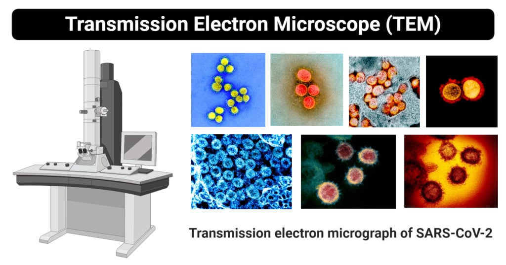
This can accurately be stated that the TEM can be used to detail the internal structures of the smallest particles like a virion particle.
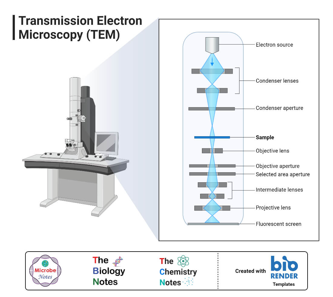
Parts of Transmission Electron Microscope (TEM)
Their working mechanism is enabled by the high-resolution power they produce which allows it to be used in a wide variety of fields. It has three working parts which include:
- Electron gun
- Image producing system
- Image recording system
Electron gun
- This is the part of the Transmission Electron Microscope responsible for producing electron beams.
- Electrons are produced by a cathode that is a tungsten filament that is V-shaped and it is normally heated. The tungsten filament is covered by a control grid known as a Wehnelt cylinder made up of a central hole which lies columnar to the tube. The cathode lies on top of or below the cylindrical column hole. The cathode and the control grid are negatively charged with an end of the anode which is disk-shaped that also has an axial hole.
- When electrons are transmitted from the cathode, they pass through the columnar aperture (hole) to the anode at high voltage with constant energy, which is efficient for focusing the specimen to produce an accurately defined image.
- It also has the condenser lens system which works to focus the electron beam on the specimen by controlling the energy intensity and the column hole of the electron gun. The TEM uses two condenser lenses to converge the beam of electrons to the specimen. The two condenser lens each function to produce an image i.e the first lens which has strong magnification, produces a smaller image of the specimen, to the second condenser lens, directing the image to the objectives.
Image- Producing system
- Its made up of the objective lens, a movable stage or holding the specimen, intermediate and projector lenses. They function by focusing the passing electrons through the specimen forming a highly magnified image.
- The objective has a short focal length of about 1-5mm and it produces an intermediate image from the condenser which are transmitted to the projector lenses for magnification.
- The projector lenses are of two types, i.e the intermediate lens which allows great magnification of the image and the projector lens which gives a generally greater magnification over the intermediate lens.
- To produce efficient high standard images, the objectives and the projector lenses need high power supplies with high stability for the highest standard of resolution.
Image-Recording System
- Its made up of the fluorescent screen used to view and to focus on the image. They also have a digital camera that permanently records the images captured after viewing.
- They have a vacuum system that prevents the bombardment or collision of electrons with air molecules disrupting their movement and ability to focus. A vacuumed system facilitates the straight movement of electrons to the image.
- The vacuumed system is made up of a pump, gauge, valves and a power supply.
- The image that is formed is called a monochromatic image, which is greyish or black and white. The image must be visible to the human eye, and therefore, the electrons are allowed to pass through a fluorescent screen fixed at the base of the microscope.
- The image can also be captured digitally and displayed on a computer and stored in a JPEG or TIFF format. During the storage, the image can be manipulated from its monochromatic state to a colored image depending on the recording apparatus eg use of pixel cameras can store the image in color.
- The presence of colored images allows easy visualization, identification, and characterization of the images.
How does a Transmission Electron Microscope (TEM) work?
From the instrumentation described, the working mechanism is a sequential process of the parts of the TEM mentioned above. To mean:
- A heated tungsten filament in the electron gun produces electrons that get focus on the specimen by the condenser lenses.
- Magnetic lenses are used to focus the beam of electrons of the specimen. By the assistance offered by the column tube of the condenser lens into the vacuum creating a clear image, the vacuum allows electrons to produce a clear image without collision with any air molecules which may deflect them.
- On reaching the specimen, the specimen scatters the electrons focusing them on the magnetic lenses forming a large clear image, and if it passes through a fluorescent screen it forms a polychromatic image.
- The denser the specimen, the more the electrons are scattered forming a darker image because fewer electron reaches the screen for visualization while thinner, more transparent specimens appear brighter.
NOTE: If the screen is moved aside, a photographic image can be captured in pixels forming a permanent image.
Preparation of specimen for visualization by TEM
The specimen to be viewed under the TEM must undergo a special preparation technique to enable visualization and creation of a clear image.
- Electrons are easily absorbed and easily scattered on solid elements, showing poor visualization for thick specimens. And therefore, very thin specimens are used for accurate and clear visualization forming a clear image as well. The specimen should be about 20-100nm thin and 0.025-0.1nm diameter, as small as that of a bacterial cell. Thin specimens allow interaction with electrons in a vacuumed space, are able to maintain their innate structure.
- To get thin slice specimens, the specimen is first fixed on a plastic material with glutaraldehyde or osmium tetraoxide. These chemical agents stabilize the structure of the cell and maintain its originality. The addition of an organic solvent like alcohol such as ethanol will dehydrate the cell completely for embedding the specimen to the plastics.
- The specimen is then permeated by adding an unpolymerized liquid epoxy plastic making it hardened like a solid block. This is where thin sections are cut from using a glass knife with a piece of special equipment known as an ultramicrotome.
- The specimen is then stained appropriately (with the appropriate stain) for the uniform scattering of electrons. The thin sections are then soaked in heavy metallic elements such as lead citrate and uranyl acetate allowing the lean and aluminum ions to bind to the cell structures. This forms an opaque layer against the electrons on the cell structures to increase contrast.
- The stained thin sections are then mounted on copper grids for viewing.
- The primary staining techniques that are applied for viewing under the TEM is Negative staining coupled with heavy metallic elements coating. The metallic coating scatters electrons which appears on the photographic film while uncoated sections and used to study bacterial, viral cell morphologies and structures.
Freeze-itching treatment:
To reduce the possible dangers of artifacts, freeze-itching is used especially for the treatment of microbial cells, unlike chemical fixation, dehydration, and embedding, where most specimens get contaminated.
- Microbial cell organelles undergo special treatment known as Freeze-itching whereby the specimens are prepared with liquid nitrogen and then warmed at -100°C in a vacuum chamber.
- The sections are then cut with a precooled knife in liquid nitrogen at -196°C. After warming up the sectioned specimen in a high vacuum for about 2 minutes, it can then coated ith platinum and carbon layer forming replicas.
- These are then be viewed under the TEM displaying more detailed internal structures of the cell in 3D.
- This step of treatment with Liquid nitrogen is known as freeze-itching.
Applications of Transmission Electron Microscope (TEM)
TEM is used in a wide variety of fields From Biology, Microbiology, Nanotechnology, forensic studies, etc. Some of these applications include:
- To visualize and study cell structures of bacteria, viruses, and fungi
- To view bacteria flagella and plasmids
- To view the shapes and sizes of microbial cell organelles
- To study and differentiate between plant and animal cells.
- Its also used in nanotechnology to study nanoparticles such as ZnO nanoparticles
- It is used to detect and identify fractures, damaged microparticles which further enable repair mechanisms of the particles.
Advantages of Transmission Electron Microscope (TEM)
- It has a very powerful magnification of about 2 million times that of the Light microscope.
- It can be used for a variety of applications ranging from basic Biology to Nanotechnology, to education and industrial uses.
- It can be used to acquire vast information on compounds and their structures.
- It produces very efficient, high-quality images with high clarity.
- It can produce permanent images.
- It is easy to train and use the Transmission Electron Microscope
Limitations of Transmission Electron Microscope (TEM)
- Generally, the TEMs are very expensive to purchase
- They are very big to handle.
- The preparation of specimens to be viewed under the TEM is very tedious.
- The use of chemical fixations, dehydrators, and embedments can cause the dangers of artifacts.
- They are laborious to maintain.
- It requires a constant inflow of voltage to operate.
- They are extremely sensitive to vibrations and electro-magnetic movements hence they are used in isolated areas, where they are not exposed.
- It produces monochromatic images, unless they use a fluorescent screen at the end of visualization.
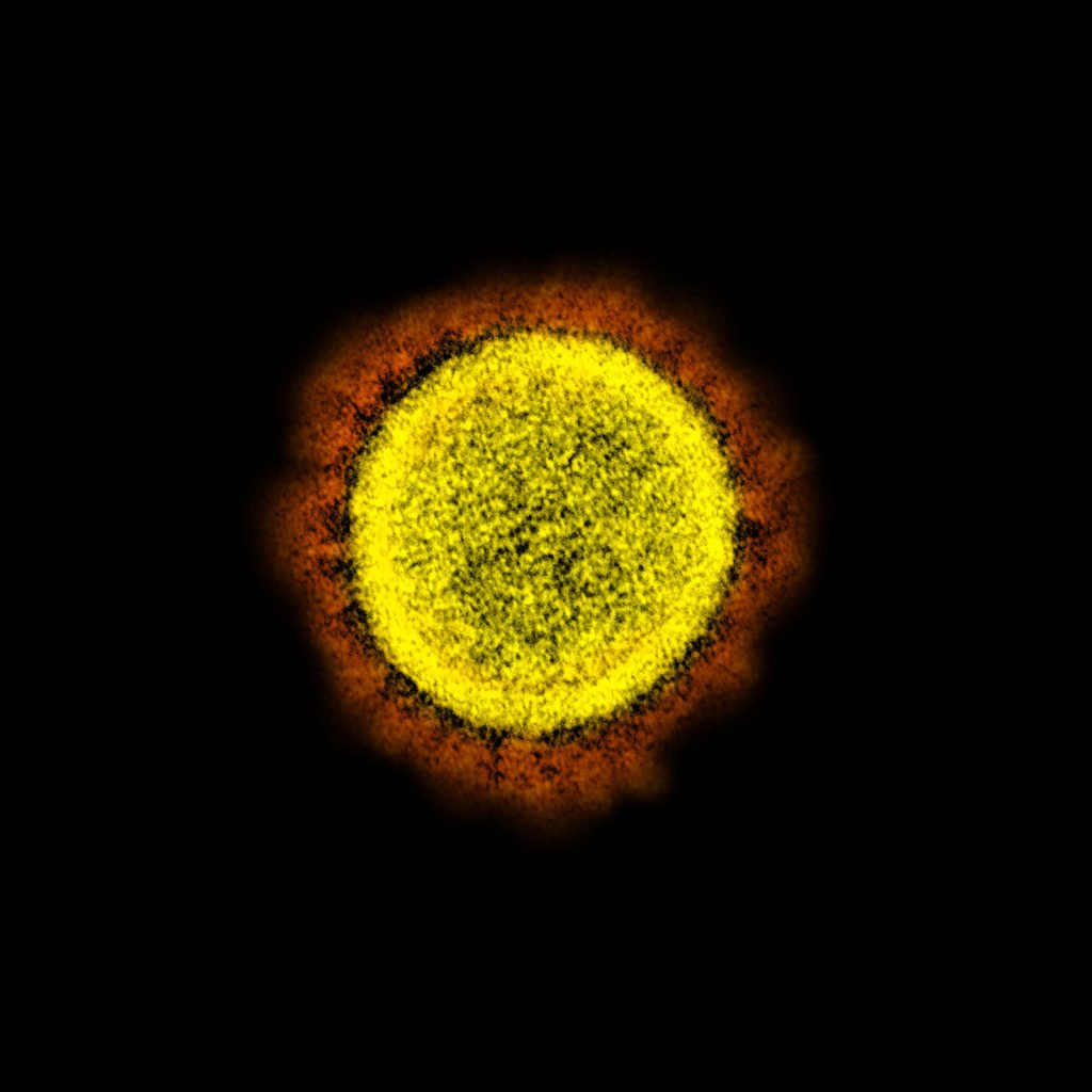
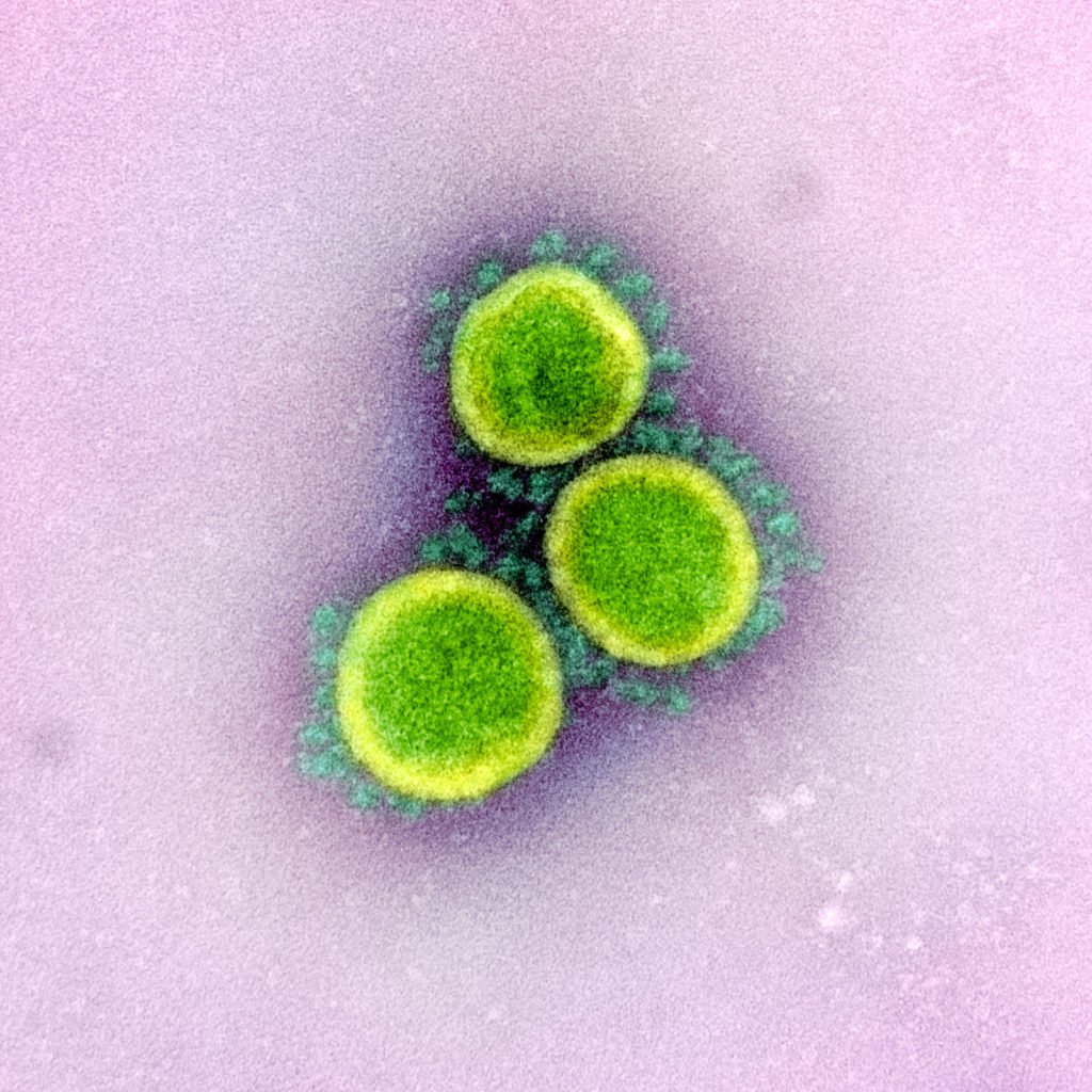
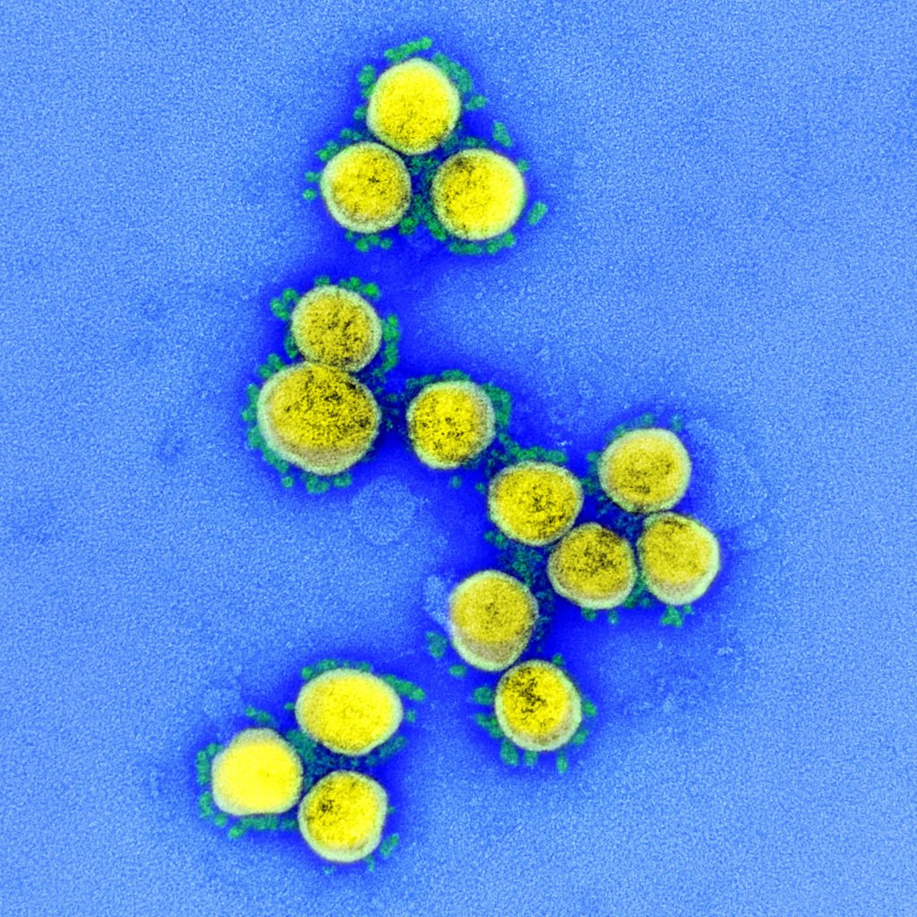
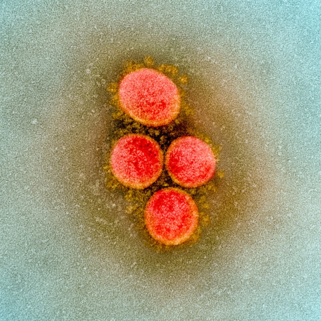
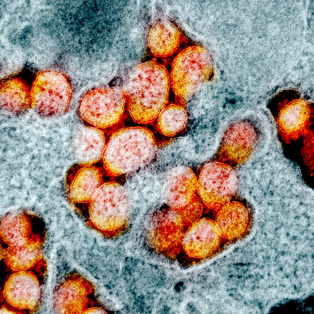
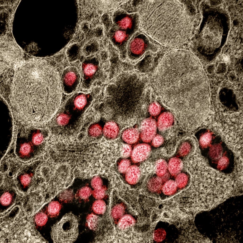
Transmission Electron Microscope (TEM) Images


0 Comments